Sender Receiver Diagram
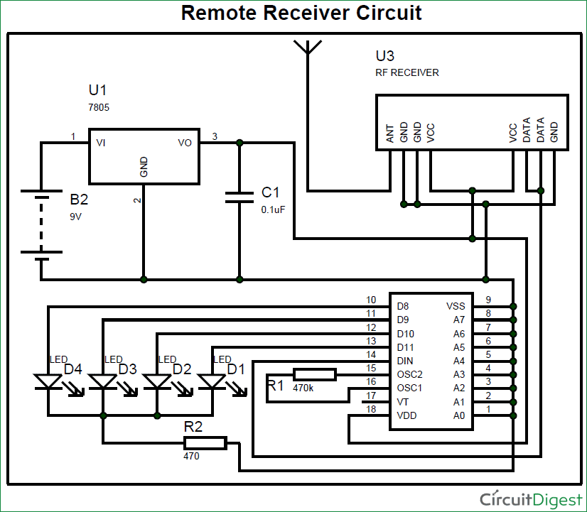
RF Transmitter and Receiver In this project, I will use RF modules with Pic 16f628a It will be a short tutorial about rf After you learn ho rf modules communicate with each other you can use these modules with pic microcontroller, ardunio or any microcontroller I controlled.

Sender receiver diagram. Dialogue Sender Flowchart Problems Downloading In some browsers the Download button in the menu above causes the document to be opened in a new tab or window rather than being downloaded If this happens, simply use the Export button on your browser to download to your desktop Email Barbara with questions b reichlin @ swbellnet. Infrared is the most commonly used wireless data transfer medium for limited range, and we already covered about simple IR Transmitter and Receiver circuitToday in this Article, we will learn how to build a Crude Wireless Audio Transfer Circuit Using IR LEDsUsing this circuit you should be able to play songs from your IPod, mobile or computer to an external speaker without having to connect. Block diagram of a basic superheterodyne radio receiver The way in which the receiver works can be seen by following the signal as is passes through the receiver Front end amplifier and tuning block Signals enter the front end circuitry from the antenna.
Use finite state machines (FSM) to specify sender, receiver state 1 state 2 event causing state transition actions taken on state transition state From current. In this diagram, the sender is a human being using their company account to send an email to someone at a different company Step A Sender creates and sends an email The envelope header also contains a 'ReplyTo' address provided by the sender that the receiver can use to reply to the sender This is analogous to the return address on. Wireless Video Transmitter and Wireless Video Receiver Our wireless video transmitters and video receivers make wireless video easy and reliable Our wireless video transmitters and wireless video receivers are the perfect solution when it is difficult or impossible to run cables and ideal for receiving video over long distances.
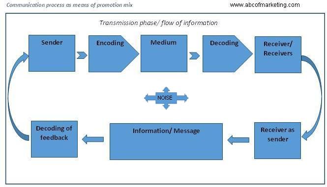
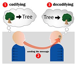
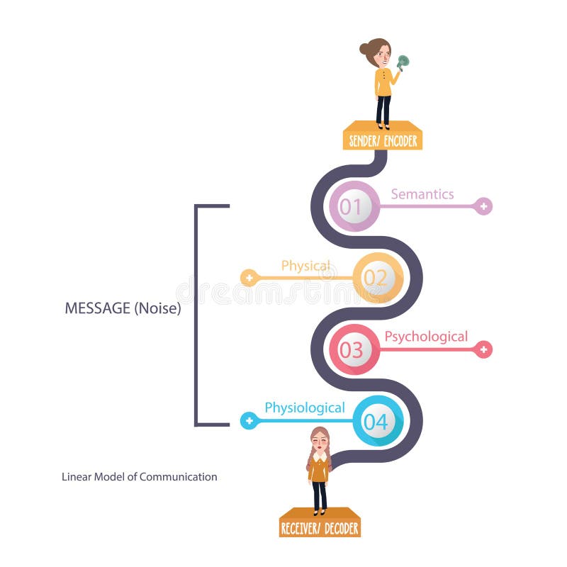
The sender puts the message into a series of symbols, pictures or words which will be communicated to the intended receiver Encoding is an important step in the communication process as wrong and inappropriate encoding may defeat the true intent of the communication process. The sendermessagechannelreceiver (SMCR) model of communication is an expansion of the ShannonWeaver model of communicationDavid Berlo created this model, which separated Shannon and Weaver's linear model into clear parts, in 1960 It has been expanded upon by other scholars Berlo described factors affecting the individual components in the communication making the communication more. The following image describes the block diagram of the IR Transmitter and Receiver In the image, the IR Transmitter emits Infrared light modulated at a particular frequency The IR Receiver will receive this modulated signal and demodulates it and sends it to the Microcontroller.
Incrementally develop sender, receiver sides of reliable data transfer protocol (rdt) consider only unidirectional data transfer – but control info will flow on both directions!. 1) If the transmission path is line of sight, the transmission/reception will be significantly improved by using Yagi directional antennas or panel antennas 2) For 5W, 10W and W transmitters, it is recommended to use antenna of at least 9dBi gain or above 3) Yagi antenna is a directional antenna It is recommended to use only if the distance between the transmitter and the receiver is a. The next step in the communication process is encoding Opens in new window, done by the sender—person who creates and shares a messageTo encode is to turn a message into a series of meaningful words and codes Before the message can be sent to the receiver, the sender needs to encode the message Because it’s the sender who initiates the communication process, he/she is primarily.
RCPT TOc3po@receivercom\r\n ACK The sender sends the RCPT TO command for c3po 250 OK \r\n ACK Receiver acknowledges RCPT TOr2d2@receivercom\r\n ACK The sender sends the RCPT TO command for r2d2 250 OK \r\n ACK Receiver acknowledges DATA\r\n ACK The sender signals the start of data by using the DATA command 354 Enter email, end with ACK. Download and unpack the rt_tcpsenderreceiverzip (for use with NI myRIO 1900) or the NIELVISIIIrt_tcpsenderreceiverzip (for use with NI ELVIS III) archive, and then doubleclick the "lvproj" file to open the project NOTE This project was written for a NI myRIO 1900 or NI ELVIS III connected by USBLAN at IP address. IR Receiver Circuit Diagram IR Receiver circuit is very simple we just need to connect a LED to the output of the TSOP1738, to test the receiver We have use BC557 PNP transistor here, to reverse the effect of TSOP, means whenever the output is HIGH LED will be OFF and whenever it detects IR and output is low, LED will be ON.
1) If the transmission path is line of sight, the transmission/reception will be significantly improved by using Yagi directional antennas or panel antennas 2) For 5W, 10W and W transmitters, it is recommended to use antenna of at least 9dBi gain or above 3) Yagi antenna is a directional antenna It is recommended to use only if the distance between the transmitter and the receiver is a. Antenna Converts the amplified signal to radio waves Radio receivers A radio receiver is the opposite of a radio transmitter It uses an antenna to capture radio waves, processes those waves to extract only those waves that are vibrating at the desired frequency, extracts the audio signals that were added to those waves, amplifies the audio signals, and finally plays them on a speaker. SMARTEYE Sender/Receiver User Manual Page A1 10 Introduction The Smarteye Sender/Receiver Reader senses an identification number coded into a Smarteye Label When a label moves past a reader, signals are sent from the reader, enabling the control unit (SEA8, Twin, SingleP, or Snet) to determine the label identification number.
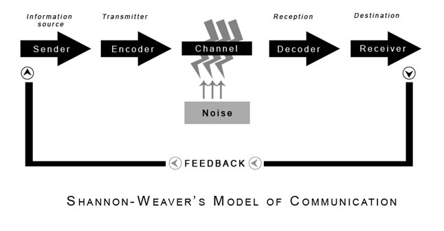
The sendermessagechannelreceiver (SMCR) model of communication, sometimes called the Berlo model, is the most basic form of communication we engage in today It's really less of a ''model. Between sender and receiver With the many ways in which communications can be encoded, channeled, and decoded, there is little wonder why so many difficulties exist when people attempt to communicate with one another Yet communication processes become more complex Discussing communication in terms of senderreceiver implies oneway. 433 MHz RF Transmitter and Receiver In many projects, we use RF modules to transmitting and receive the data because it has a high volume of applications than IR In order to draw the attention of the recipient computer for the message received from the sender computer, an audio beeping system is interfaced from the MAX232 Transmitter pin.
SMARTEYE Sender/Receiver User Manual Page A1 10 Introduction The Smarteye Sender/Receiver Reader senses an identification number coded into a Smarteye Label When a label moves past a reader, signals are sent from the reader, enabling the control unit (SEA8, Twin, SingleP, or Snet) to determine the label identification number. Ultrasonic receiver circuit The receiver circuit (Fig2) is built around a single decade counter CD4017 (IC4) and a few discrete components To check the working of the transmitter, it is necessary to downconvert the 40kHz signal into 4kHz to bring it in the audible range By using the receiver, the 40kHz ultrasonic transmitter can be tested. Wireless Camera Transmitter And Receiver Circuit Diagram Four Channels Wireless Remote Transmitter Receiver Diy wireless audio sender circuit eleccircuit com 2 4ghz wifi wireless a v security camera transmitter receiver car anti theft wireless alarm circuit diagram world tv transmitter circuit using only 2 transistors operates from 12v.
Radio RF receiver FM transmitter amplifier schema Power Amplifier Preamplifier Audio mixer Audio Equalizer DC Protection Headphone Amplifier Vu Meter Automatic message sender for CB S chematics wiring diagram circuits schema electronic projects Basic. The complete circuit Diagram including the Transmitter and Receiver part for this project is shown in the images below Below pictures showing the RF Transmitter Circuit with Breadboard setup And below ones showing the RF Receiver Circuit with Breadboard setup As you can see the RF Transmitter Circuit consists of the Encoder IC and RF. Infrared is the most commonly used wireless data transfer medium for limited range, and we already covered about simple IR Transmitter and Receiver circuitToday in this Article, we will learn how to build a Crude Wireless Audio Transfer Circuit Using IR LEDsUsing this circuit you should be able to play songs from your IPod, mobile or computer to an external speaker without having to connect.
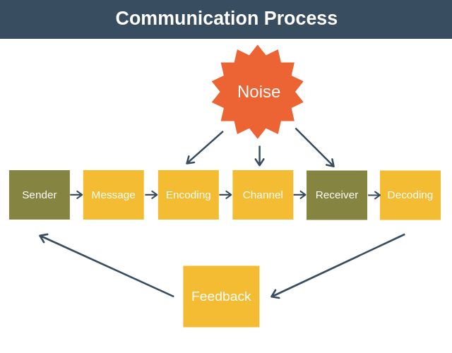
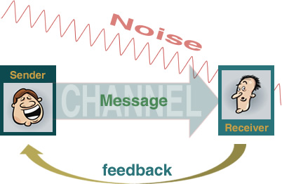
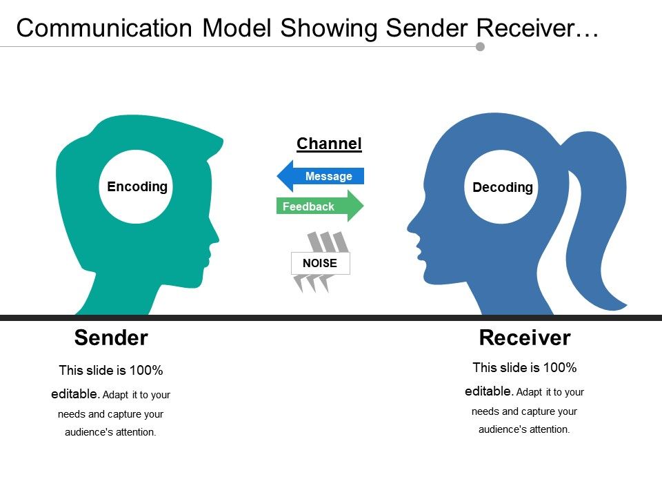
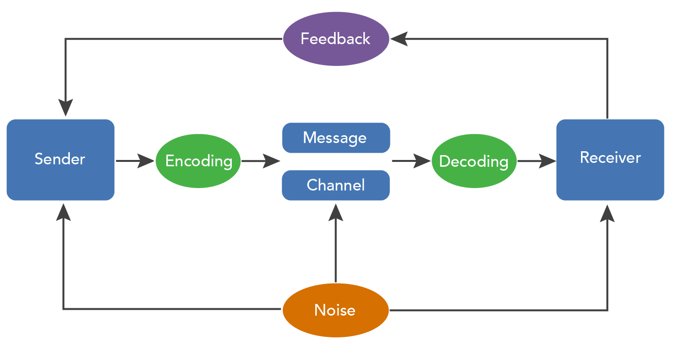
The circuit of an ultrasonic transmitter and receiver uses an IC CD4017 decade counter The transmitter circuit is designed with D flip flop IC and twodecade counter ICs and a few major componentsThe circuit design generates stable 40kHz signals, which are transferred by the transducer. Antenna Converts the amplified signal to radio waves Radio receivers A radio receiver is the opposite of a radio transmitter It uses an antenna to capture radio waves, processes those waves to extract only those waves that are vibrating at the desired frequency, extracts the audio signals that were added to those waves, amplifies the audio signals, and finally plays them on a speaker. Sender 2 Transmission 3 Noise 4 Receiver 5 Feedback Process # 1 Sender Communication starts with the sender, who is the initiator of the message After generating an idea, the sender encodes it in a way that can be comprehended by the receiver.
Wire the receiver module to another Arduino by following the next schematic diagram Note always check the pinout for the receiver module you’re using Usually, there are labels next to the pins Alternatively, you can also take a look at your module’s datasheet Receiver Sketch Upload the code below to the Arduino connected to the receiver. Receiver The receiver is one who is intended to receive the message sent by sender Feedback Feedback constitutes the information which the sender receives about the receiver’s reaction to the message that has been generated Response and feedback complete the twoway process of communication. RCPT TOc3po@receivercom\r\n ACK The sender sends the RCPT TO command for c3po 250 OK \r\n ACK Receiver acknowledges RCPT TOr2d2@receivercom\r\n ACK The sender sends the RCPT TO command for r2d2 250 OK \r\n ACK Receiver acknowledges DATA\r\n ACK The sender signals the start of data by using the DATA command 354 Enter email, end with ACK.
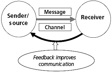
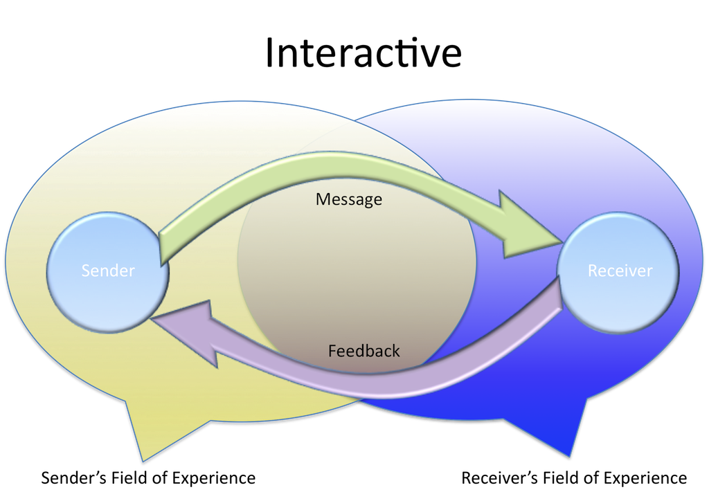
The communication is a two way process one way for the sender and the other for the receiver The return loop is as important as the delivery loop The importance of the sender and the receiver is equal They have to be properly balanced for the smooth communication A trader is a good communicator and a good listener as well. In the image above, the vertical axis can be seen as the voltage going to the IR LED in the remote and the horizontal axis is time So when the LED is on, it is blinked (modulated) at 38 kHz and when it is off, no voltage is applied. Infrared is the most commonly used wireless data transfer medium for limited range, and we already covered about simple IR Transmitter and Receiver circuitToday in this Article, we will learn how to build a Crude Wireless Audio Transfer Circuit Using IR LEDsUsing this circuit you should be able to play songs from your IPod, mobile or computer to an external speaker without having to connect.
The message or content is the information that the sender wants to relay to the receiver Additional subtext can be conveyed through body language and tone of voice Put all three elements together — sender, receiver, and message — and you have the communication process at its most basic. Between sender and receiver With the many ways in which communications can be encoded, channeled, and decoded, there is little wonder why so many difficulties exist when people attempt to communicate with one another Yet communication processes become more complex Discussing communication in terms of senderreceiver implies oneway. The sender puts the message into a series of symbols, pictures or words which will be communicated to the intended receiver Encoding is an important step in the communication process as wrong and inappropriate encoding may defeat the true intent of the communication process.
Antenna Converts the amplified signal to radio waves Radio receivers A radio receiver is the opposite of a radio transmitter It uses an antenna to capture radio waves, processes those waves to extract only those waves that are vibrating at the desired frequency, extracts the audio signals that were added to those waves, amplifies the audio signals, and finally plays them on a speaker. Circuit Diagram As it is a wireless communication project, the circuit consists of a Transmitter part and a Receiver part The circuit for the Transmitter part of the project is shown below And the circuit for the Receiver part of the project is shown below Components Required Transmitter Part Arduino UNO (or any other Arduino board). The receiver is technically called as the decoder The receiver must understand the message or in other words, must decode it or interpret it and must react or produce a desired response, which must be received by the sender The communication channel can be represented by the following diagram Communication is always made with some purpose.
The complete circuit Diagram including the Transmitter and Receiver part for this project is shown in the images below Below pictures showing the RF Transmitter Circuit with Breadboard setup And below ones showing the RF Receiver Circuit with Breadboard setup As you can see the RF Transmitter Circuit consists of the Encoder IC and RF. The complete circuit Diagram including the Transmitter and Receiver part for this project is shown in the images below Below pictures showing the RF Transmitter Circuit with Breadboard setup And below ones showing the RF Receiver Circuit with Breadboard setup As you can see the RF Transmitter Circuit consists of the Encoder IC and RF. The circuit of an ultrasonic transmitter and receiver uses an IC CD4017 decade counter The transmitter circuit is designed with D flip flop IC and twodecade counter ICs and a few major componentsThe circuit design generates stable 40kHz signals, which are transferred by the transducer.
Receiver The receiver is one who is intended to receive the message sent by sender Feedback Feedback constitutes the information which the sender receives about the receiver’s reaction to the message that has been generated Response and feedback complete the twoway process of communication. Antenna Converts the amplified signal to radio waves Radio receivers A radio receiver is the opposite of a radio transmitter It uses an antenna to capture radio waves, processes those waves to extract only those waves that are vibrating at the desired frequency, extracts the audio signals that were added to those waves, amplifies the audio signals, and finally plays them on a speaker. When the receiver confirms to the sender massage that he has received and understood it carefully, actually, the communication process is completely done 8 Noise Noise is any type of disruption that interferes with the interpretation of information from the.
Decoding is the process of adapting the symbols encoded by the sender Feedback;. Communication Process Diagram Example Context 1 –The sender must decide and articulate the message he/she wants to send 2 –The sender must decide what is the best channel through which to send the message, such as written, verbal, and facetoface 3 –The message is often degraded due to sound, internal and/or external 4 –Did the receiver. SMARTEYE Sender/Receiver User Manual Page A1 10 Introduction The Smarteye Sender/Receiver Reader senses an identification number coded into a Smarteye Label When a label moves past a reader, signals are sent from the reader, enabling the control unit (SEA8, Twin, SingleP, or Snet) to determine the label identification number.
When the receiver confirms to the sender massage that he has received and understood it carefully, actually, the communication process is completely done 8 Noise Noise is any type of disruption that interferes with the interpretation of information from the. The complete circuit Diagram including the Transmitter and Receiver part for this project is shown in the images below Below pictures showing the RF Transmitter Circuit with Breadboard setup And below ones showing the RF Receiver Circuit with Breadboard setup As you can see the RF Transmitter Circuit consists of the Encoder IC and RF. Ultrasonic receiver circuit The receiver circuit (Fig2) is built around a single decade counter CD4017 (IC4) and a few discrete components To check the working of the transmitter, it is necessary to downconvert the 40kHz signal into 4kHz to bring it in the audible range By using the receiver, the 40kHz ultrasonic transmitter can be tested.
Receiver The receiver is the second person in the conversation, who the sender is talking to Feedback Facetoface communication involves lots of feedback, as each person takes turns to talk If someone’s message is not heard to to noise, they can ask for clarification easily. A very simple TV audio video transmitter circuit can be designed using this schematic diagram This TV audio video transmitter circuit can be used to transmit video signals from VCR ( or some other device ) to a TV without using any cable The TV audio video transmitter circuit combines line level audio and video signals, and transmits the resulting signal up to 300 feet. The sender and receiver transmits communication signals to request and acknowledge establishment of circuits Data Transfer Once the circuit has been established, data and voice are transferred from the source to the destination The dedicated connection remains as long as the end parties communicate.
1) If the transmission path is line of sight, the transmission/reception will be significantly improved by using Yagi directional antennas or panel antennas 2) For 5W, 10W and W transmitters, it is recommended to use antenna of at least 9dBi gain or above 3) Yagi antenna is a directional antenna It is recommended to use only if the distance between the transmitter and the receiver is a. Radio RF receiver FM transmitter amplifier schema Power Amplifier Preamplifier Audio mixer Audio Equalizer DC Protection Headphone Amplifier Vu Meter Automatic message sender for CB S chematics wiring diagram circuits schema electronic projects Basic. The sequence diagram clearly displays the sender and receiver of the message and also the sequence of the messages exchanged which provide a clear vision of the interaction between them Thereby the sequence diagram reveals how the actors interact with the system to execute all or part of the use case Sequence diagram has components like.
Q Tbn And9gcsl5flwyt6fp7daiufb7gso4eyst1ia6yfsmsdgikds5g2xb4ew Usqp Cau
Domino Effect

The Process Of Communication Organizational Behavior And Human Relations
Sender Receiver Diagram のギャラリー

Communicating With Workplace Teams Change Factory

The Communication Process

Circle Communication Network With Sender And Receiver Ppt Powerpoint Presentation Diagrams Powerpoint Templates
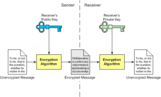
Public Key Cryptography
Solved Q1 Explain The Following Network Based Scheduling Give An Example That Fits Such Description Q2 Explain Why We Need The Feedback In The Course Hero

Light Activated Signaling In Dna Encoded Sender Receiver Architectures Biorxiv
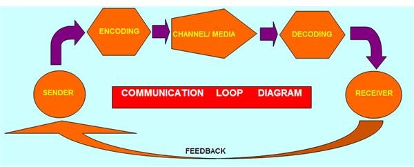
Free Sample Of A Communication Loop Diagram Brighthub Project Management
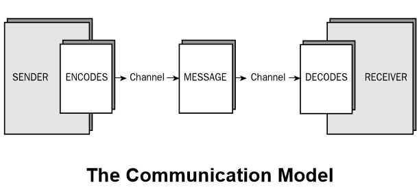
Back To Basics The Basic Communication Model Mayecreate Designmayecreate Design

Mq Commands To Setup Two Way Communication Between Two Queue Managers On Sender And Receiver Channels

Rest Your Sap Rest Adapter Issues With Some Troubleshooting Tips Sap Blogs
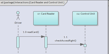
Lifelines Messages And Activations Enterprise Architect User Guide

Oral Communication Diagram Quizlet
Rf Transmitter And Receiver Circuit Diagram
Communication Is A Two Way Process Of Exchanging Ideas Or Information Between Two Human Beings Explain This Statement With Help Of Diagram M M R Cse
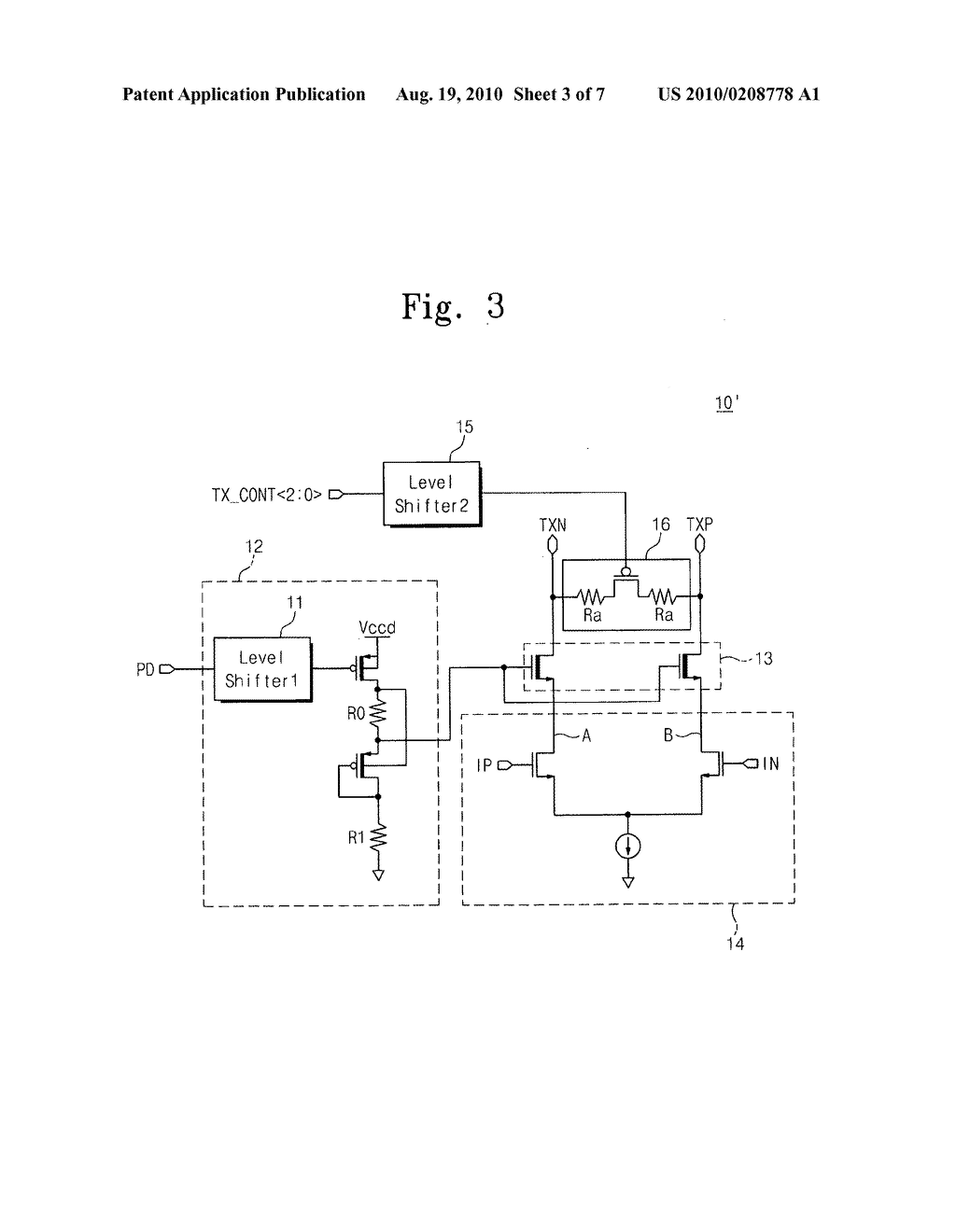
Transmitter Device And Hdmi Sender Receiver Device Including The Same Diagram Schematic And Image 04

Sequence Diagrams

1 Communication Theory Sender Channel Receiver Communication In Physiotherapy

Roles Of The Sender Receiver And Adversary In An Insecure Download Scientific Diagram

Geektieguy Why Agile Software Development Works

What Is Flow Control In Networking
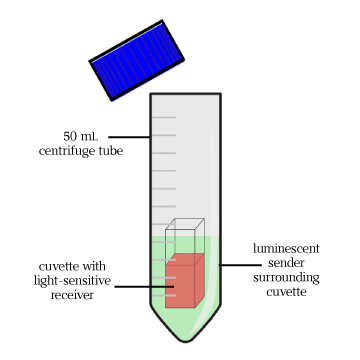
Team Penn Communication 15 Igem Org

Appendix B

Communication Model Having Sender Message Channel And Receiver Presentation Powerpoint Templates Ppt Slide Templates Presentation Slides Design Idea

Pdf The Sender Receiver Model And The Targeting Process Semantic Scholar

The Encode Decode Model Of Communication

5 Main Processes Of Communication With Diagram
Explain The Communication Model Process Relative To Promotion Mix Of An Organisation
Context And Scope Gitbook

Understanding Communication Skills From Mindtools Com
How The Communication Process Works Communication Training

Networked Media Open Specifications Legacy Technical Overview Nmos

Communication And Management Principles Of Management
Shannon And Weaver Model Of Communication

Transactional Model Of Communication Businesstopia

Chain Of Responsibility Pattern Wikipedia

Delivery
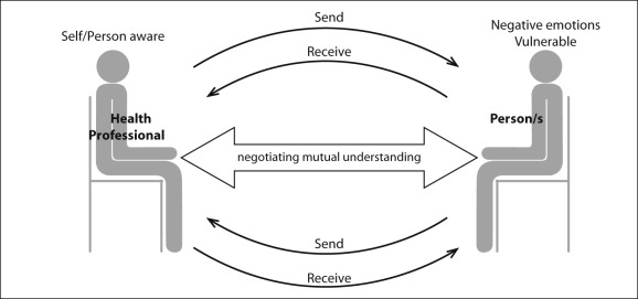
Communication Theory Sender Channel Receiver Communication In Occupational Therapy

Block Diagram For Sender And Receiver Download Scientific Diagram

Role Of The Sender In Communication Process Ifioque Com
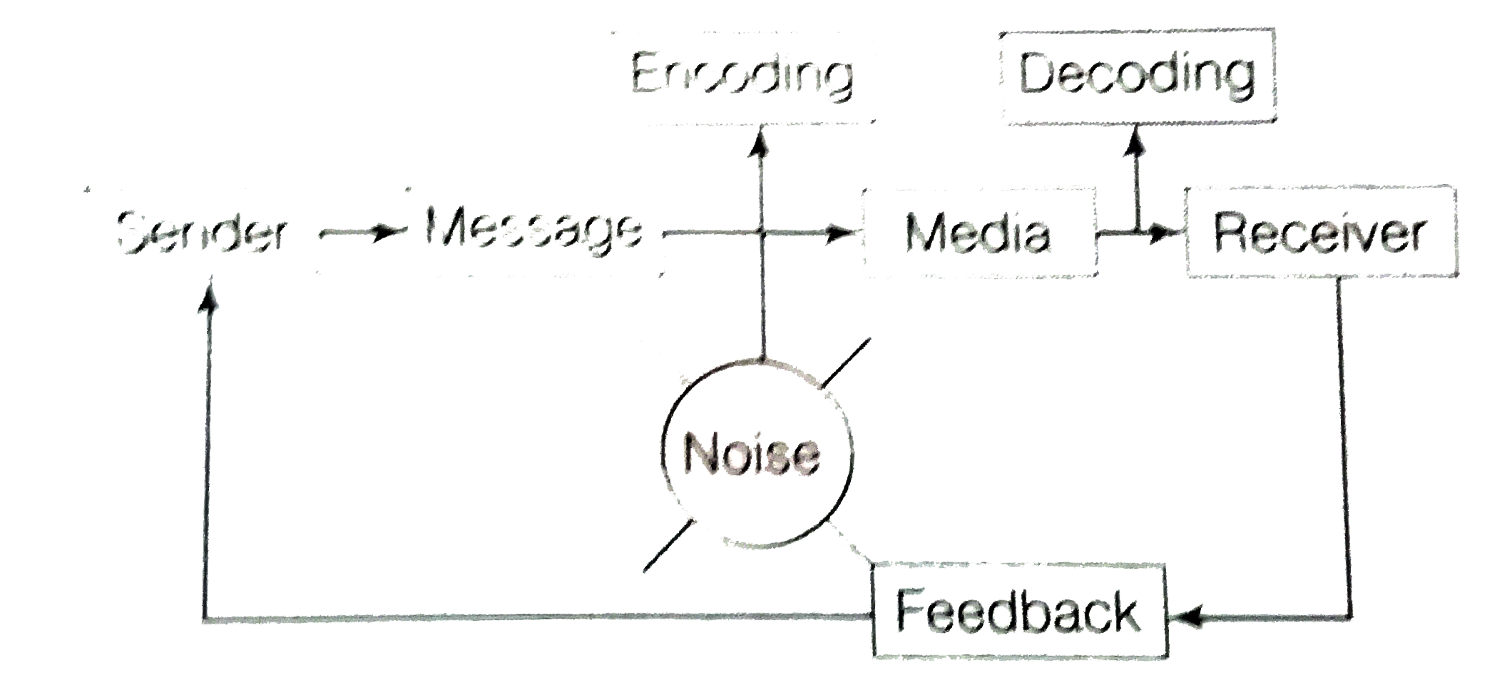
Discuss In Brief The Process Of Communication And Show The Process
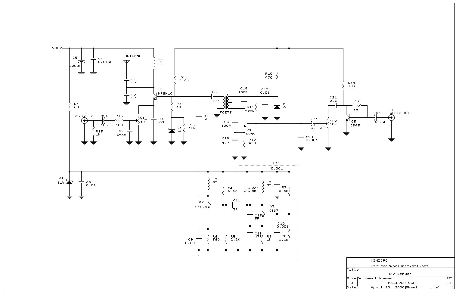
Wireless Video Transmitter
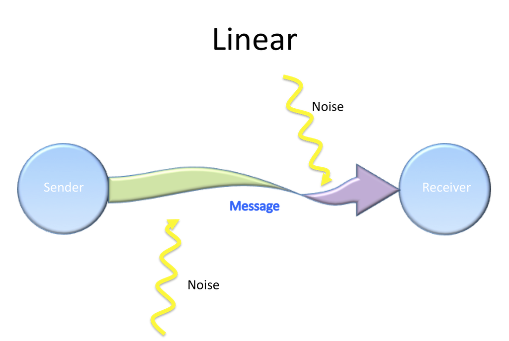
Chapter 1 Introducing Communication The Evolution Of Human Communication From Theory To Practice
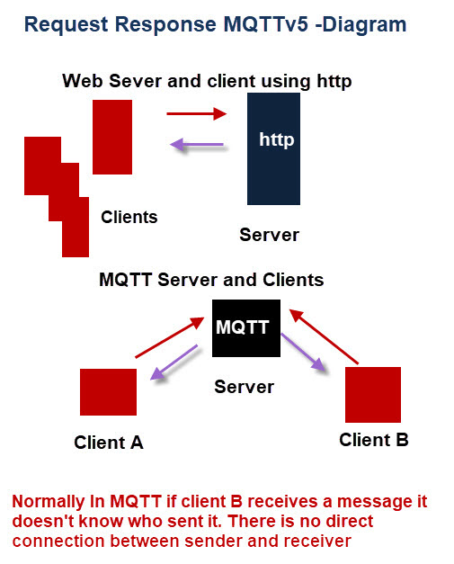
Understanding And Using Mqtt V5 Request Response
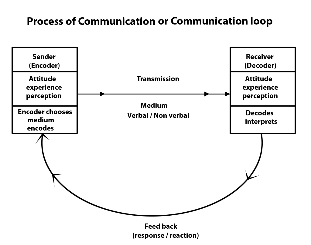
Communication Loop The Process Of Communication
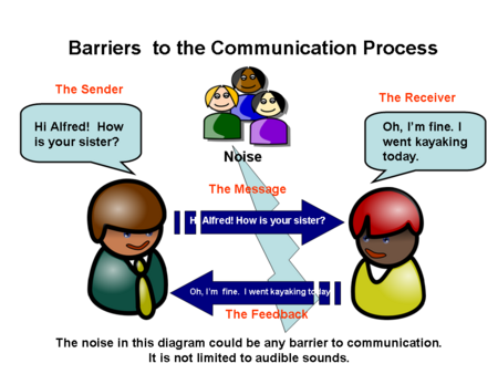
Vussc Content Tourism Applying Effective Communication Skills The Process Of Communication Wikieducator
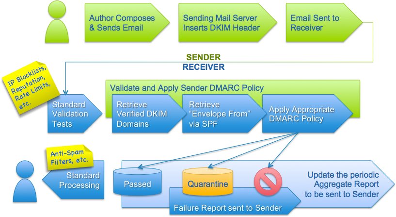
Overview Dmarc Org
The Communication Process Thecommunicationprocess Com
Q Tbn And9gcress7hsnkn8mnnsjzixhoajpqmbu1la2yzojjcaubeiu7d3cti Usqp Cau
Introducing Adaptive Payments

Consequences Of Misdiagnosis False Identifying Of The Relationships Types In The Class Diagram Stack Overflow

3 Ways To Choose A Powerful And Effective Communication Style Doncrawley Com

Udp Sender And Receiver And Udp Ping Application
Components Of Data Communication System Geeksforgeeks

Communication Theory Sender Channel Receiver Communication In Occupational Therapy

Flow Control Stop Wait And Stop Wait Arq Protocol Studytonight

Information Flow Chart With Sender Message And Receiver Ppt Powerpoint Presentation Portfolio Format Ideas Powerpoint Templates
Schramm S Model Of Communication Wilbur L Schramm Was A

Light Activated Signaling In Dna Encoded Sender Receiver Architectures Biorxiv
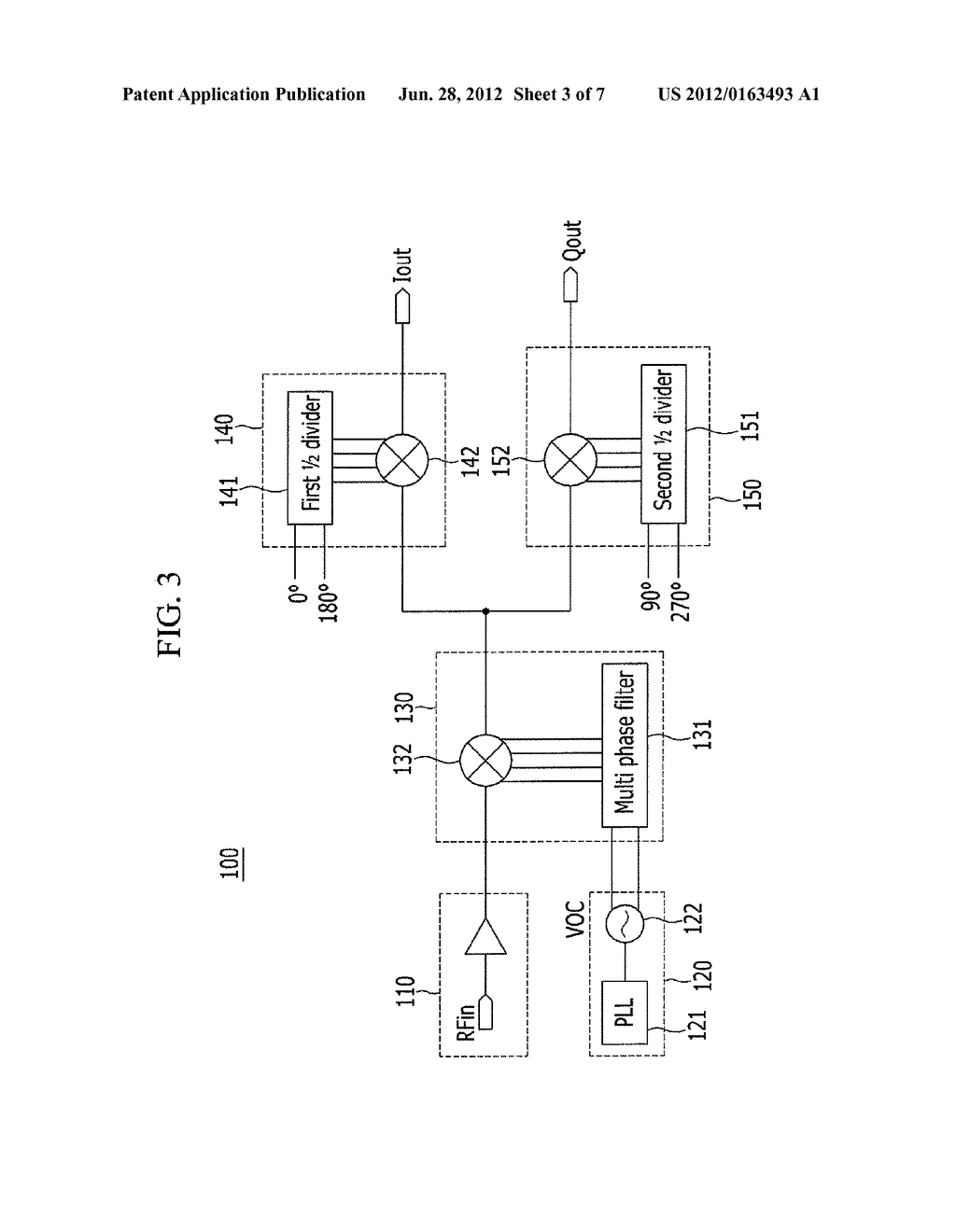
Ultrahigh Frequency I Q Sender Receiver Using Multi Stage Harmonic Mixer Diagram Schematic And Image 04
:max_bytes(150000):strip_icc()/what-is-communication-process-1689767_FINAL-069d65e4e1414e5c917379c42a537a66.png)
The Basic Elements Of The Communication Process

Communication Sender Channel Receiver Communication In Physiotherapy

Diagram Illustrating How Sender And Receiver Determine And Exchange Download Scientific Diagram

What Is Network Security Model In Cryptography Binary Terms

Tcp Ip Sender And Receiver And Tcp Ping Application
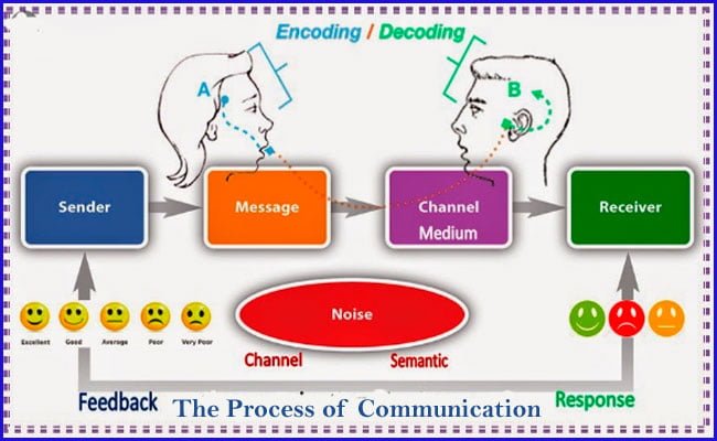
The Process Of Communication With Definition And Diagram

What Is Communication Process Definition And Meaning Business Jargons

What Is Stop And Wait Protocol
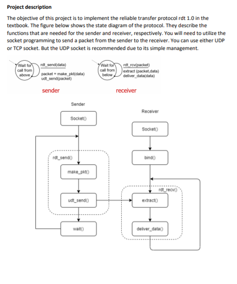
Project Description The Objective Of This Project Chegg Com

Draw A Diagram Of Communication Cycle And Explain It Brainly In

Solved Q No 4 05 Marks Consider The Below Given Sequen Chegg Com

Build A Shared Communication Channel With Multiple Senders And Receivers Matlab Simulink
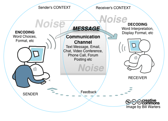
A Model Of Communication

Language Barriers To Effective Communication

Autosar Sender Receiver Statuses Queued Communication The Distek Blog
Models Of Communication Wikipedia

Novell Documentation Zenworks For Servers 3 Understanding The Sender Receiver
Sender Receiver Message Stock Illustrations 1 Sender Receiver Message Stock Illustrations Vectors Clipart Dreamstime
Implementing Sender Receiver Java Proxy Scenario In Sap Po Pi Sap Blogs

Sender Receiver Distributing The Load Of Data Collection

Morse Sender And Receiver For Line Transmission Electrical Engineering Stack Exchange
Communication Model Showing Sender Receiver Channel Feedback Powerpoint Slide Images Ppt Design Templates Presentation Visual Aids

In The Class Discussion We Talked About Communication Making A Diagram That Look A Lot Like This Picture In The Diagram There Communication Messages Receiver
Sender Receiver High Resolution Stock Photography And Images Alamy
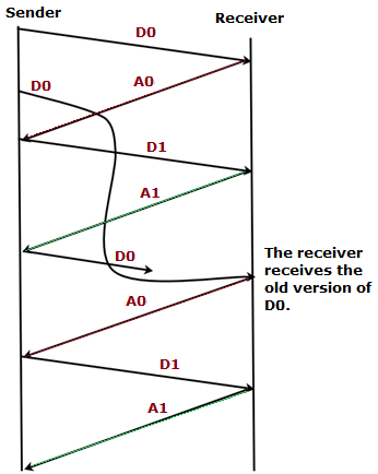
Consider The Rdt 3 0 Protocol Draw A Diagram Sr2jr

Distributed Queuing Components

Style Linear Single 5 Piece Powerpoint Presentation Diagram Infographic Slide Powerpoint Presentation Images Templates Ppt Slide Templates For Presentation
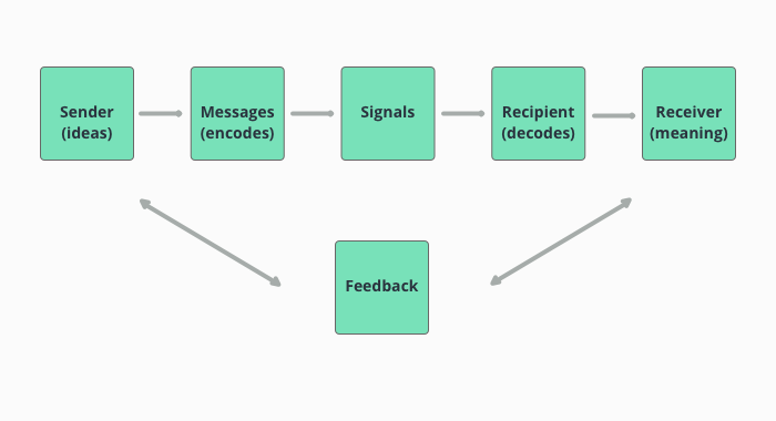
The 6 Streamlined Stages Of The Communication Process

Communication Models

Interface Uhr Core Msg Messagerouter
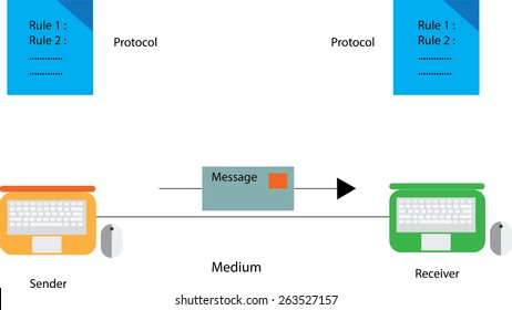
Communication Sender Receiver Stock Illustrations Images Vectors Shutterstock
1

Jagged Delta Asymmetry In Notch Signaling Can Give Rise To A Sender Receiver Hybrid Phenotype Pnas

Sliding Window Protocol Set 3 Selective Repeat Geeksforgeeks

Jms Architecture And Jms Api Architecture Journaldev

The Communication Model Of A Facebook Live Video Broadcast Based On The Shannon Weaver Model A Practical Example For Football Clubs Sports Business Research
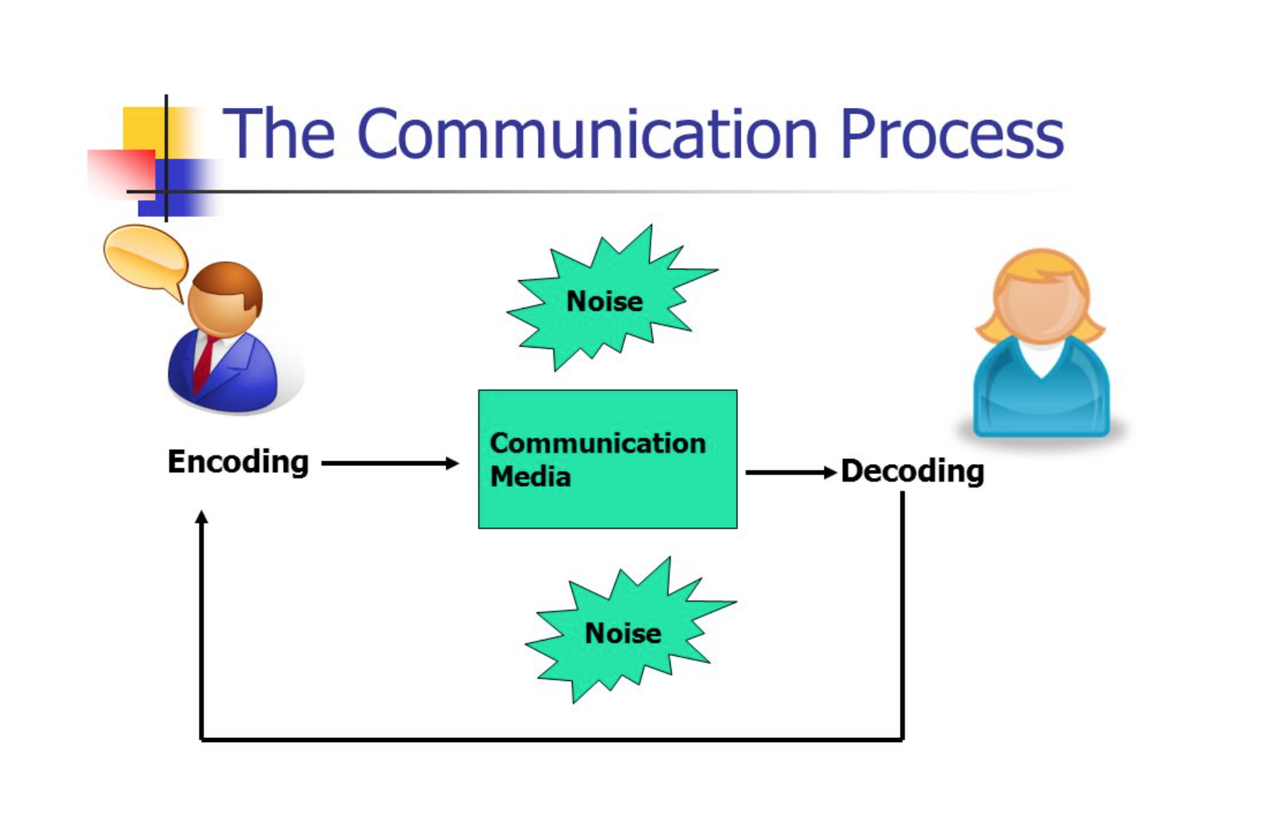
Communications Process Encoding And Decoding Communication For Business Professionals
The Process Of Communication Organizational Behavior And Human Relations
Chapter 1 Introducing Communication The Evolution Of Human Communication From Theory To Practice

Odust Sender Receiver Overall Architecture Download Scientific Diagram

Rfrbauxws02 Wireless Sender Receiver Label Diagram 001 Ai Beautiful Enterprise


